
Algorithm Research of Magnetometer Assisted Inertial Navigation System for Mobile Robots

1 Science and Technology on Near-Surface Detection Laboratory, Wuxi, China
2 Peking University Shenzhen Graduate School, Shenzhen, China.
Abstract
Mobile robots have broad application prospects in military, industrial, agricultural, commercial, transportation, and logistics fields. The core problem of mobile robot lies in the autonomous navigation ability of mobile robot. Inertial navigation system based on MEMS sensor is one of the research hotspots in the field of inertial navigation in recent years and one of the main research directions in the future. Aiming at the positioning of the mobile robot, this paper adopts the magnetometer assisted inertial navigation system, the navigation system consisting of a three-axis accelerometer, a three-axis gyroscope and a three-axis magnetometer. The heading is calculated with three sensors, the velocity error is compensated, and calculate the position. In this paper, an Extended Kalman Filter for mobile robot navigation system is proposed to improve the position accuracy of the navigation system. Experiments are carried out to verify and analyze the filter with the experimental results. with the experimental results.
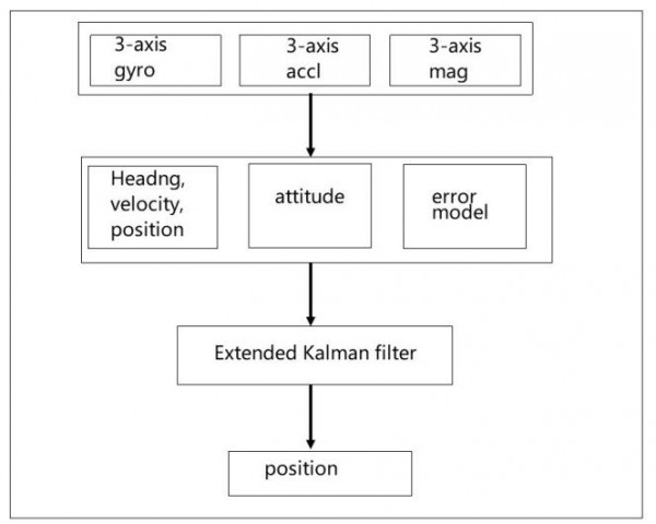
Figure 1: Inertial navigation system
Since the accuracy of MEMS inertial sensors is relatively low and there are many random errors, long-term operation will cause error accumulation, and the inertial navigation system composed of them cannot operate independently for a long time. The characteristics of the magnetometer are opposite to those of the MEMS inertial sensor, which is less accurate than the MEMS sensor in a short time, but it does not accumulate errors over time. Add a magnetometer to assist the inertial navigation system to correct the attitude. The inertial navigation system of IMU combined with magnetometer has the advantages of small size and low power consumption. This paper introduces the research on the positioning algorithm of magnetometer and IMU, designs a navigation system for mobile robot, and designs extended kalman filter to solve more accurate position information.
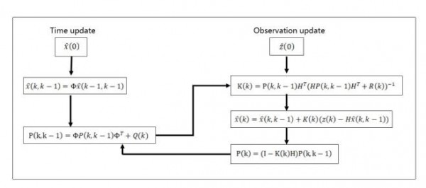
Figure 2: Extended
Kalman filtering An algorithm that uses the linear system state equatio to optimally estimate the state of the system by inputting and outputting observation data through the system. The observed data includes the effects of noise and interference in the system, so the filtering process can also be considered as the optimal estimate. Kalman filtering does not require that both signal and noise are assumptions for a stationary process. For system disturbances and observation errors (noise) at each moment, as long as some appropriate assumptions are made about their statistical properties, the observation signals containing noise are processed. An estimate of the true signal with the smallest error can be found in the average sense. In this paper, the measurement of magnetometer, gyroscope and accelerometer is directly integrated to calculate attitude Angle, velocity and position, and the optimal solution is obtained through EKF filter, so as to obtain a more accurate position.
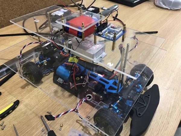
Figure 3: Arduino car
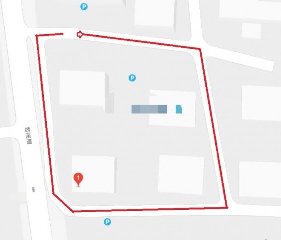
Figure 4: Experimental environment
The carrier of this experiment is Arduino car, as shown in Figure 3. Mount the sensor on the carrier. The sensor used is BEWIS SENSNG‘s HEC-395, a 9-axis sensor that includes a 3-axis accelerometer, a 3-axis magnetometer, and a 3-axis gyroscope. The output frequency is set to 20 Hz. In this experiment, GPS is used as the standard quantity, and the experimental results are compared with the GPS output. The GPS provides the heading, velocity and position, and the GPS output frequency is 20 Hz. The experimental environment is shown in Figure 4. The carrier is around the building, and the square motion path has both
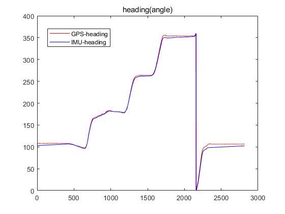
Figure 5: Comparison of heading
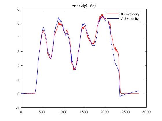
Figure 6: Comparison of velocity
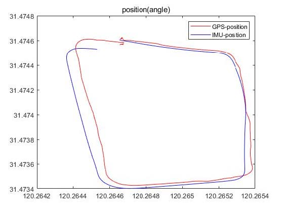
Figure 7: Comparison of position
Figure 5, Figure 6, and Figure 7 are comparisons of experimental results and standard quantities. The red line is the standard quantity provided by GPS, and the blue line is the result of extended Kalman filtering.
Media Contact
Company Name: Wuxi Bewis Sensing Technology LLC
Contact Person: Flowe Zhang
Email: Send Email
Phone: +86 15050672146
Address:Building 30, No.58 Xiuxi Road
City: Wuxi
State: Jiangsu
Country: China
Website: https://www.bwsensing.com

